Rotating crib

Introduction
In October I had the chance, with my family, to visit Rome Maker Faire 2016 where I heard about the Wireless Power Contest. At that time I was evaluating with my wife and children the possibility to set-up a rotating Christmas crib, powered by the electric outlet, with flashing lights on the scene.
One point in our discussion was the way to power the LED lights put on the rotating platform without using a battery (we wanted the set to be temporized).
The wireless power kit was a possible option, so I decided to submit the project idea that has been selected and we finally received the kit.
The preparation of the project has been an opportunity to spend some time with my family, having each of us involved in some part, and working all together with a defined objective in mind.
Kit list
We tried to realize the project using spare components and some recycled cardboard pieces.
For another project I purchased some pieces of Node MCU microcontrollers, and I decided to recycle one for this activity. Maybe we will add some extra features in the future (e.g. remote control the rotation of the set).
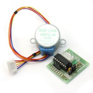
I also grabbed a spare 28BYJ-48 Stepper Motor with ULN2003 Driver from another project : for the same project (a laser scanner) I 3D printed a motor connector, that I used to fix the rotating platform to the stepper.
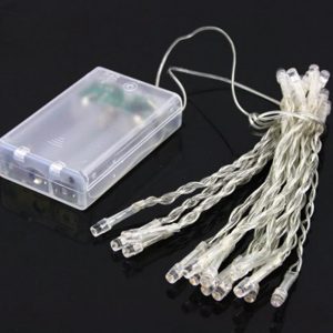
The LED lights came from previous Christmas decorations.
The printed crib parts were found on the Internet (link in the hardware components section).
The fixed part of the system was mounted on a clamp that simplified the overall set-up.
Project execution
Now some details on the project phases: all activities have been completed in a few days, having, as I said before, each of us involved in some parts.
Project Team
- Dad (myself)
- Mom
- Matteo (9)
- Valerio (7)
The Nativity figures
Mom coordinated the crib statues preparation. First the templates have been downloaded and printed. Then with the help of Valerio and Matteo they patiently cut and glued all parts.


The platform
We cut a thin 60 cm diameter cardboard sheet that we used as rotating platform.
Valerio managed the platform painting and the scene layout activities. We digged holes with a screwdriver for the LED lights and, when the platform was ready, we used some scotch tape to fix wires on the bottom.
I modified the LED lights battery case adding two wires to the BAT+ and BAT- pins in order to power the platform using the Wireless Power Kit.

The two pins were connected to the OUT and GND pins on the FT1235M Wireless Power Receiver (whose antenna was soldered before).
Finally I assembled the platform on a piece of honeycomb, on top of which I also glued the Wireless Power Receiver and the motor connector.
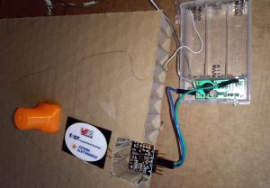
The fixed components
First I soldered the Wireless Power Transmitter antenna to the FT1235M module.
Then I connected the 28BYJ-48 Stepper Motor and ULN2003 Driver using the dedicated socket, then interconnected the motor driver to the Node MCU as follows:
- IN1 -> D6
- IN2 -> D7
- IN3 -> D2
- IN4 -> D1
- – -> GND
- + -> VU
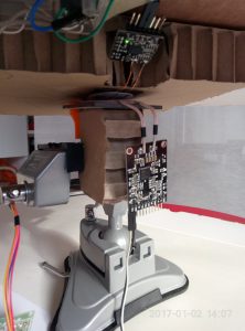
Then I locked the motor and a piece of honeycomb cardboard to the clamp and I sticked the Wireless Power Transmitter to the cardboard, facing top.

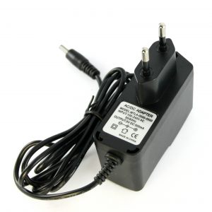
Both the NodeMCU module and the Wireless Power Transmitter have been connected to the 5V 2A DC power adapter.
Programming
I used the ARDUINO IDE to program the NodeMCU module. I first tried the legacy stepper library, but I realized quite soon that there was something wrong with the stepper not moving as expected.
Then I found on the Internet another library and I decided to give it a try.
The results are better than before and more or less what I was expecting to have. The stepper control is quite precise and fluent.
The short program I wrote is reported in the Software section below.
Assembling and testing
I connected the platform to the motor and did some tests to position the wireless transmitter antenna in the best position.

My first intention was to give the platform a continuous 360° rotation, but then I preferred to have it move back and forth, activating the wireless power kit while the set is in the center of the movement. This policy can be easily changed in my trivial code.
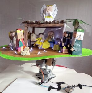
The results
The overall thing was surprisingly fast and everything worked as expected after a few minutes of testing and tuning.
The Wireless Power Kit behaves as expected and the final result looks really nice.
Finally it is time for Matteo to take some pictures and prepare the video for the Wireless Power Contest.
Whatever the contest results, this project has been for my family a great opportunity to spend some time together playing and learning new things.
Schematics
The picture below shows the interconnection between the Node MCU, the motor driver and the stepper.
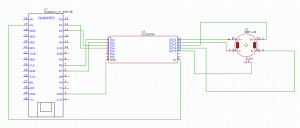
Please note that the NodeMCU module I used is able to provide on the VU pin 5V voltage when powered by the USB. As far as I know other NodeMCU modules, produced by other manufacturers, are not able to generate this signal. This means that in that case the + pin of the ULN2003 should be connected to the DC power supply directly.
In the following diagram the interconnection between the Wireless Power Kit modules and the LED fairy lights is reported.
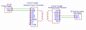
List of hardware used in the project
- FT1235M Wireless Power Receiver + antenna

- FT1235M Wireless Power Transmitter + antenna

- 28BYJ-48 Stepper Motor with ULN2003 Driver
- Node MCU microcontroller

- 5V 2A DC power supply
- 20 LEDs battery operated Christmas Lights
- 3D printed 28BYJ-48 motor connector ( http://www.thingiverse.com/thing:702470 – part center_axe_MINIMAL.stl)
- Crib paper templates ( http://jacques-mylittlehouse.blogspot.it/2010/12/bible-paper-toys-book-1-nativity.html )

- Clamp

- 60×60 cm cardboard sheet
- honeycomb cardboard sheet
Software
- Arduino IDE
- Arduino Library for 28BYJ-48 ( http://www.instructables.com/id/Arduino-Library-for-28BYJ-48-Stepper-Motor-and-ULN/?ALLSTEPS )
The code
Below the Arduino code used for the project. It requires the installation of the 28BYJ-48 control library:
#include <StepperMotor.h>
StepperMotor motor(D1,D2,D6,D7);
void setup(){
motor.setStepDuration(50);
}
void loop(){
motor.step(2048);
delay(2000);
motor.step(-2048);
delay(2000);
}